
Some water softeners recharge on a predetermined schedule, but other water softeners recharge when they feel like it. If your water softener is the latter kind, then you might want to somehow get notified each time that it decides to recharge. This article describes a successful design and implementation of a system to monitor such recharging.
Many readers already know how water softeners work, but here is a bit of background. The water entering a home might be “hard” water, meaning it has some dissolved calcium or magnesium ions. This hard water enters the water softener and passes through a bed of ion exchange beads. The beads are made of a resin having binding sites that have been filled with sodium ions. The binding sites grab the magnesium and calcium ions and release the sodium ions into solution. This process continues as water flows through the softener, until such time as most or all of the binding sites have been “taken” by the magnesium and calcium ions.
At this point it is necessary to “recharge” the resin. In this recharge process, several steps take place:
-
- Valves open and close in such a way as to “bypass” the water softener, meaning that hard water is made available to the house.
- Hard water is passed “backwards” through the resin bed to loosen the beads. This “backwash” might last ten minutes. The effluent exits through a drain line.
- Brine is drawn from a brine tank and is passed through the resin bed. The sodium ions in the brine attack the binding sites of the resin, dislodging the calcium and magnesium ions and filling the binding sites. The effluent exits through a drain line. This “recharge cycle” might last 73 minutes.
- Hard water is passed relatively slowly through the resin bed, with a goal of rinsing some of the brine from the resin bed. The effluent exits through a drain line. This “slow rinse” might last three minutes.
- Hard water is passed faster through the resin bed, with a goal of rinsing all of the remaining brine from the resin bed. The effluent exits through a drain line. This “fast rinse” might last four minutes.
- Another backwash takes place, lasting perhaps one minute. The effluent exits through a drain line.
- Another fast rinse takes place, lasting perhaps one minute. The effluent exits through a drain line.
- The brine tank gets refilled.
- Valves open and close in such a way as to cease the “bypass” so that soft water is once again made available to the house.
As mentioned above, some water softeners recharge on a predetermined schedule. The likely consequence of this is:
-
- Sometimes it might turn out that the recharge happens later than one would have wished. It might turn out that the moment has passed at which most all of the binding sites have been “taken” by the magnesium and calcium ions, meaning that after this moment, the water entering the house is hard water.
- Sometimes it might turn out that the recharge happens earlier than one would have wished. It might turn out that plenty of the binding sites had not yet been “taken” by the magnesium and calcium ions. This would mean that salt gets wasted. Not only that, but the recharge process uses up a lot of water. So this also means that water gets wasted.
Ideally each recharge cycle would be “just right”, happening no sooner nor later than the ideal time. And this is the point of the water softeners that recharge “when they feel like it.” The way this is done is to place a water flow meter in the outlet flow path. The controller is configured with the “capacity” of the resin bed, and with the measured “hardness” of the incoming water. These two values permit an estimate of the volume of water that is likely to use up all of the resin binding sites. The controller measures the volume of water passing through since the most recent recharge cycle, and when that volume has nearly reached the estimate, the controller carries out another recharge cycle. In this way, hopefully the recharge cycle will be neither sooner nor later than the ideal time.
In a typical water softener of this type, the controller also keeps track of the time of day, so that the recharge cycle can be timed to start at, say, 2AM.
With a water softener of this type, a recharge cycle might happen, say, ten days after a previous recharge cycle, if lots of daily water use happens to take place. (Maybe the house is full of guests.) And then a recharge cycle might happen, say, forty days after a previous recharge cycle, if not very much daily water use happens to take place. (Maybe a vacation leaves the house empty for a while.)
Having set this background, it will be recalled that this article began with the notion that you might want to somehow get notified each time that the water softener decides to recharge. This article describes a successful design and implementation of a system to monitor such recharging.
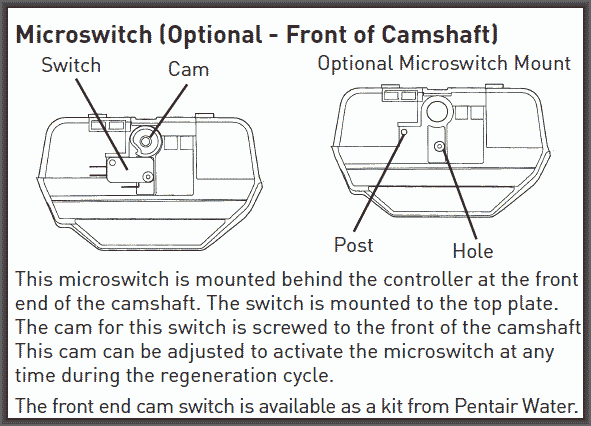
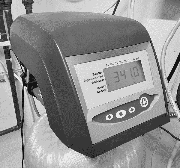
The water softener that is the subject of this article has a Pentair Autotrol 762 controller and a Pentair Autotrol 255 valve body (installation manual). The manual says you can get a kit from Pentair that includes a cam and microswitch, shown at right. The cam is said to be screwed to one end of a camshaft. A lobe of the cam is said to operate the microswitch.
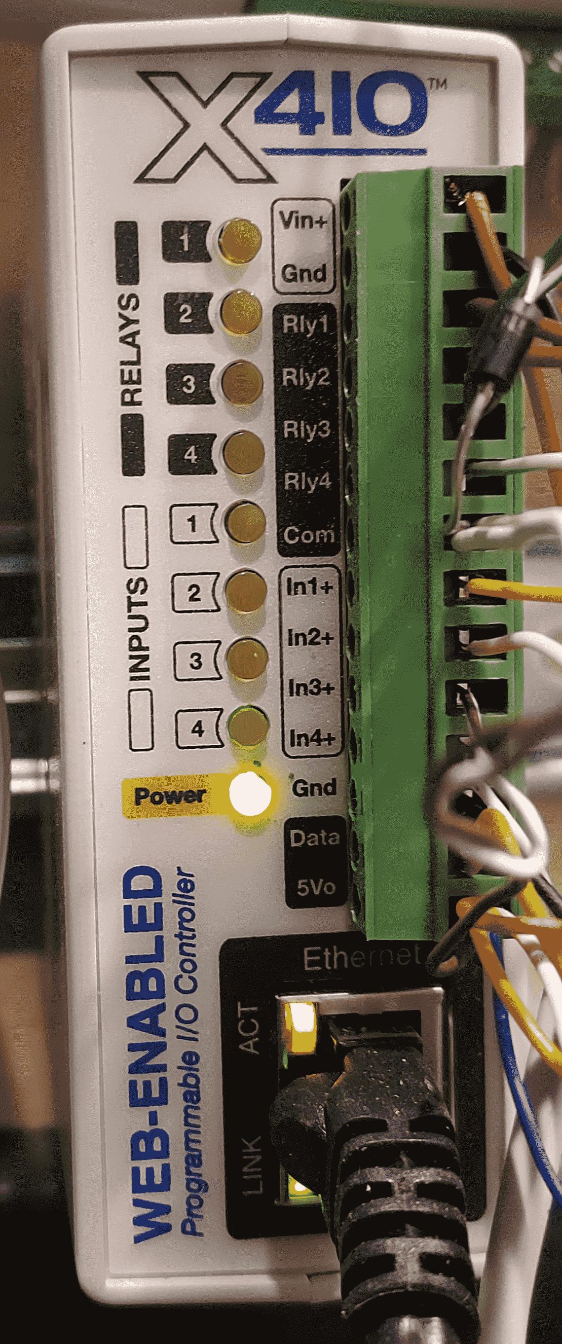
It would be easy to run a couple of wires from the microswitch to a suitable telemetry device such as a Xytronix X-410 home automation controller, shown at right. This controller could then log the event of a recharge cycle being carried out, and could send an email notification of the event. (This controller has four digital inputs, each of which can make good use of “dry” switch contacts such as would be provided by the microswitch.)
It turns out, however, that it is impossible to get this kit. Pentair does not actually make the kit available. Lots of companies sell replacement parts for this Autotrol 255 valve body, but none of them has this cam kit.
The microswitch is an industry-standard shape and size, so that is not the problem. The problem is the cam. One could consider trying to 3D-print the cam, except that there is no trustworthy design document to use. One could consider simply carving a cam by hand, perhaps with repeated test-fits on the cam shaft and relative to the micro switch. This would be a lot of fuss and bother, and might not be reliable. The screw securing the cam to the end of the camshaft might work loose, or might turn out not to be the right size of screw for the hole at the end of the camshaft.
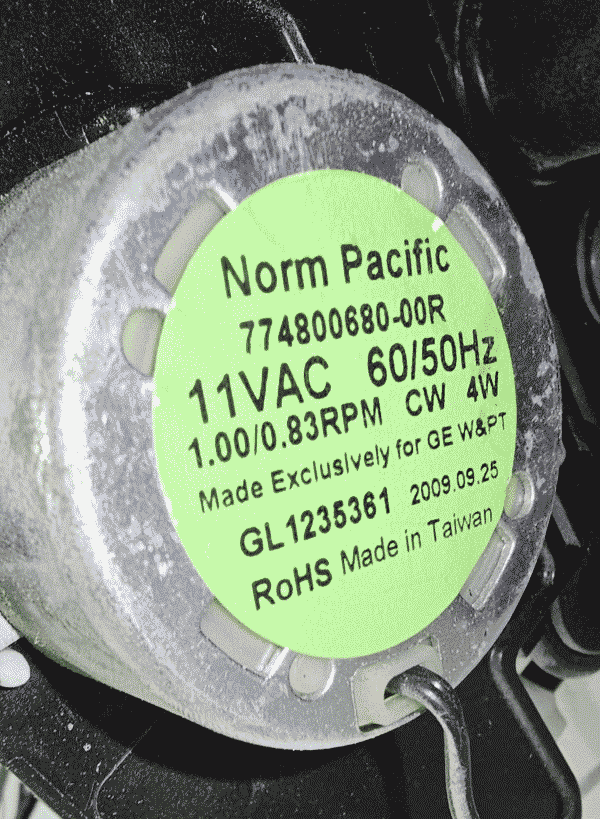
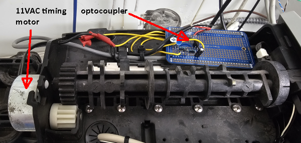
So I felt that I had to figure out some other way to sense the event of a recharge cycle. The most promising line of attack presented itself in this motor (shown at right) which operates the camshaft in the valve body. I could detect when the motor is actuated by noting the presence of electric power on the lines that power this motor.
A typical way to do this might be simply to put the coil of a relay in parallel with this motor. But there are at least four reasons not to follow this path:
-
- The solid-state switch or relay that sends power to this motor might be close to the edge of its current rating, and the additional current drawn by the relay might harm the switch or relay.
- The source of AC power employed by this controller might be close to the edge of its current rating, and the additional current drawn by the relay might harm the the AC power supply.
- The solid-state switch or relay might rely upon a snubber diode to absorb recoil from the inductive energy storage in the switched load (here, the motor and the relay). The added inductive energy storage of the relay coil might harm the snubber diode, then leading to potential harm to the switch or relay.
- Inexpensive and commonly available relays that are designed to be powered by AC tend to require 24VAC or 120VAC. I was not able to find any relay designed to be powered by 11VAC or 12VAC. There are of course many inexpensive 12VDC relays, but I did not feel comfortable trying to power a 12VDC relay with AC power.
Of course it might turn out that the relevant electrical components in the controller are sufficiently conservatively rated that the first three points just made might turn out to be safely ignored. But the controller is a sealed unit, so one cannot readily do even a visual inspection of the components. And no schematic or component parts list is available.
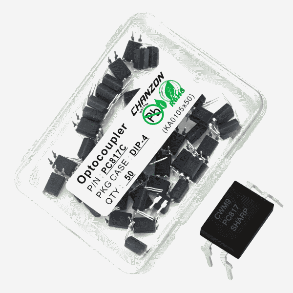
When I was in my formative years, some decades ago, there was no such thing as an optocoupler. When optocouplers first became available they were very expensive. But nowadays a box of fifty optocouplers (shown at right) can be purchased for $8, meaning that they cost 16¢ each. (You can see a spec sheet.) So I decided to try to design a suitable circuit that could receive 11VAC and that could provide an open-collector output. It turns out that with the Xytronix controller, a digital input can make good use of the open-collector output of an optocoupler.

At right you can see the schematic that I eventually arrived at with a bit of trial and error. You can see the Pentair Autotrol 762 controller 11 which provides switched 11VAC power to the camshaft actuator motor 12. I rectified the AC power using a diode 13 and electrolytic capacitor 14. This yielded about 16VDC. The LED (light-emitting diode) in the optocoupler 18 lights up nicely with 15 mA so a current-limiting resistor 17 with a value of 1KΩ works well. I like to have blinky lights whenever possible, so I added a blue LED 16 (perhaps evocative of blue-colored water) and gave it its own current-limiting resistor 15. The open-collector output of the optocoupler 18 gets connected to a +5VDC source at the Xytronix X-410 controller 19 and to one of its digital inputs.
In a testbed setup using a couple of 9V batteries to simulate AC power, I was astonished to realize that the current-limiting resistors were actually getting hot to the touch when in service. Later when I connected the circuit to the actual 11VAC power, the resistors were only slightly warm to the touch. Still I realized I needed to pay attention to the power rating of the resistors. Fortunately it turned out that I had used ¼-watt resistors and the power dissipated would likely be about 237 mW, just barely within spec. Later what I learned is that with this water softener, the motor is only turned on for about 5-27 seconds at a time. This means that even if my current-limiting resistors were to get a bit warm, it would not last very long and then the resistors could cool down. You can see the finished circuit board at right. It turned out that there is plenty of extra room within the housing of the Pentair Autotrol 255 valve body, and there are plenty of tie-downs within the valve body so that cable ties may be used to dress all of the new wiring well away from the camshaft and other moving parts.
Connecting everything together, it worked! I received a series of sixteen emails letting me know that the timing motor had been actuated eight times, each time for just a few seconds. I was thus able to work out the duration of each step in the recharge process, as detailed at the start of this article. Here you can see the log events:
| time | event | function | cycle duration | motor on duration |
| 16:44:03.47 | motor on | 27 seconds | ||
| 16:44:30.22 | motor off | backwash | 10 minutes | |
| 16:54:30.07 | motor on | 15 seconds | ||
| 16:54:44.81 | motor off | brine draw | 73 minutes | |
| 18:07:44.54 | motor on | 8 seconds | ||
| 18:07:52.86 | motor off | slow rinse | 3 minutes | |
| 18:10:52.56 | motor on | 11 seconds | ||
| 18:11:03.79 | motor off | fast rinse | 4 minutes | |
| 18:15:03.56 | motor on | 16 seconds | ||
| 18:15:19.32 | motor off | backwash | 1 minute | |
| 18:16:19.05 | motor on | 13 seconds | ||
| 18:16:32.48 | motor off | fast rinse | 1 minute | |
| 18:17:32.05 | motor on | 21 seconds | ||
| 18:17:53.40 | motor off | brine refill | 13 minutes | |
| 18:31:26.05 | motor on | 5 seconds | ||
| 18:31:30.96 | motor off | return to service |
The next thing that I realized is that eventually I might not feel the need to receive all sixteen emails. Maybe a single email would suffice. So I configured the Xytronix controller to start a two-hour timer when the input got triggered, and wrote a business process rule that said that a trigger event arising during the timer interval would not give rise to an email. This meant that I would receive only the first of the would-be sixteen emails.