
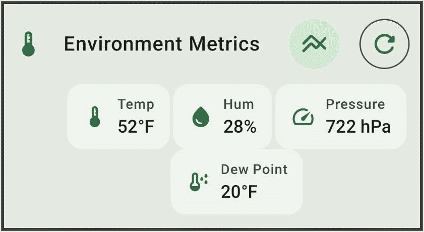
Recently I added an environmental sensor to a rooftop solar meshtastic node. This provides telemetry of temperature, humidity, and barometric pressure. In this article I describe what was required to accomplish this.
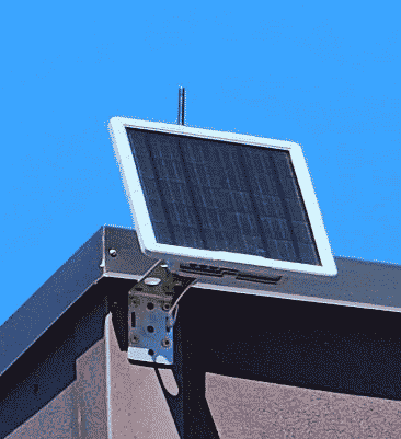
The starting point was that recently I deployed a rooftop solar meshtastic node.
Meshtastic (Wikipedia article, community web site) is an open-source volunteer-supported protocol and platform.
The device requires no cell towers, no internet, and no electrical power. It provides meshtastic connectivity to some twenty square miles of a rural area. It is a SenseCAP Solar Node P1-Pro (manufacturer’s web page, Amazon page).
After some time I realized that this device is made so that one can add a sensor for temperature, humidity and barometric pressure. The sensor is a BME280 (manufacturer’s web page). It is astonishingly small (2.5 mm by 2.5 mm) and draws astonishingly little electrical power (3.6 μA) and is strikingly inexpensive at less than $8 for a complete development board.
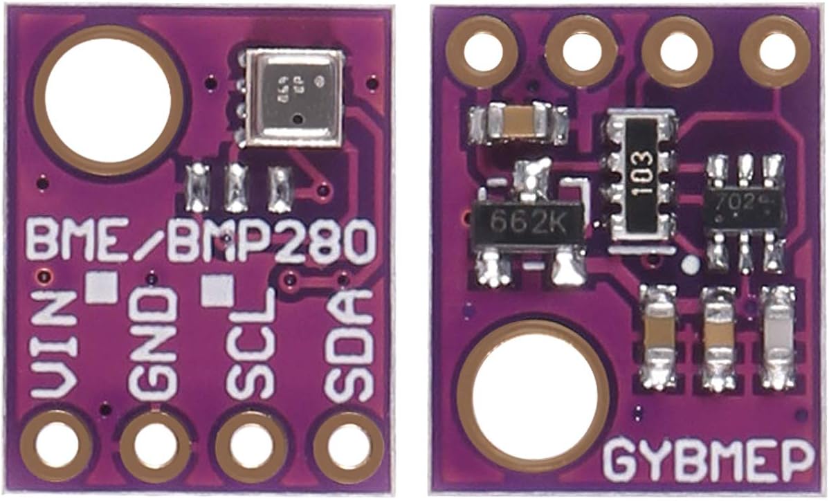
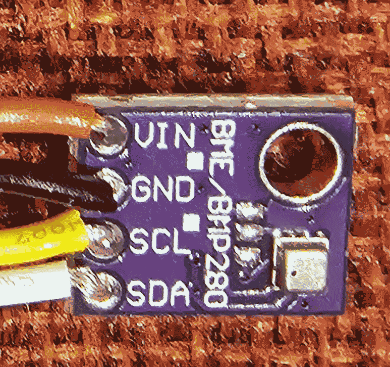
You can see the front and back of the development board (called “GYBMEP”) here. At left is the sensor side of the board. The sensor (a small silver-colored square) is at top right. Across the bottom of the board, four terminals may be seen — VIN (5 volts), GND, SCL (clock), and SDA (data).
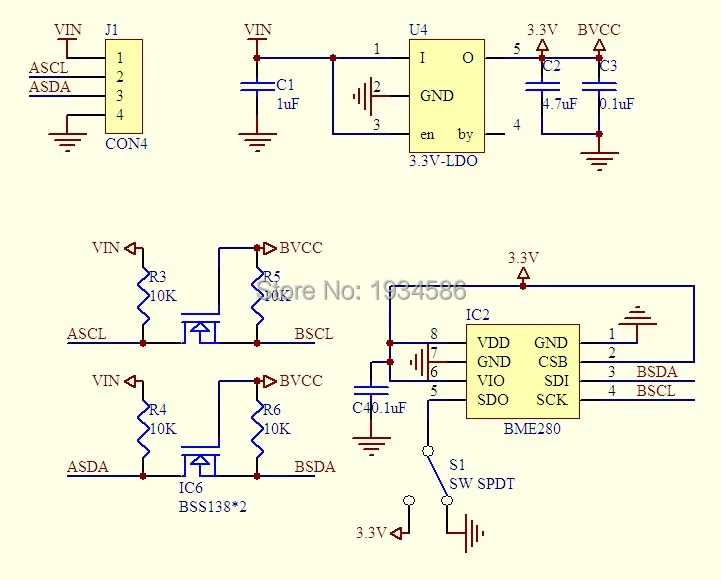
You can see a schematic of the GYBMEP board at right.
It turns out that there is a sort of informal industry standard called “Grove” (sponsor web page) for a four-wire bus permitting one or more sensors to be connected to a device. What I needed to do is find a Grove cable and solder it to this circuit board. This required that I learn which Grove pin performs which function. The answer turns out to be:
-
- Grove pin 1 – ground (customarily black)
- Grove pin 2 – 5 volt power (customarily red)
- Grove pin 3 – SDA (I2C data, customarily white)
- Grove pin 4 – SDC (I2C clock, customarily yellow)
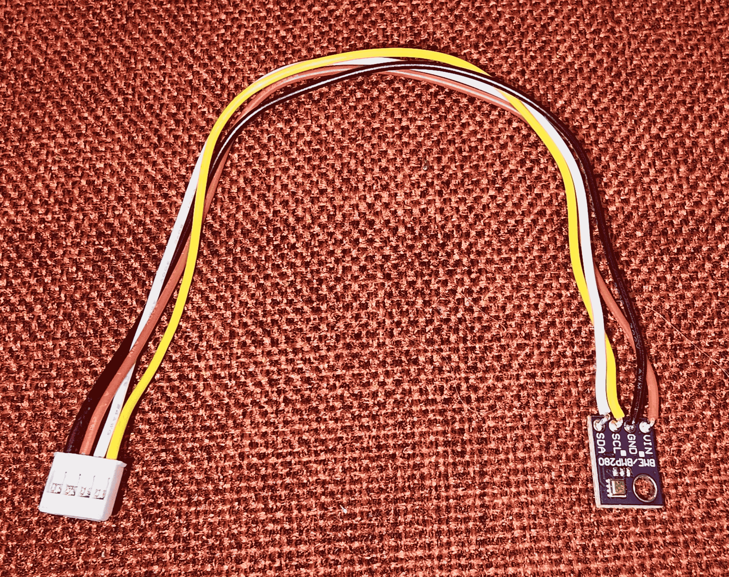
So I soldered the four wires of a Grove cable to the sensor board, as shown at right. The result was a sensor cable assembly as seen here.
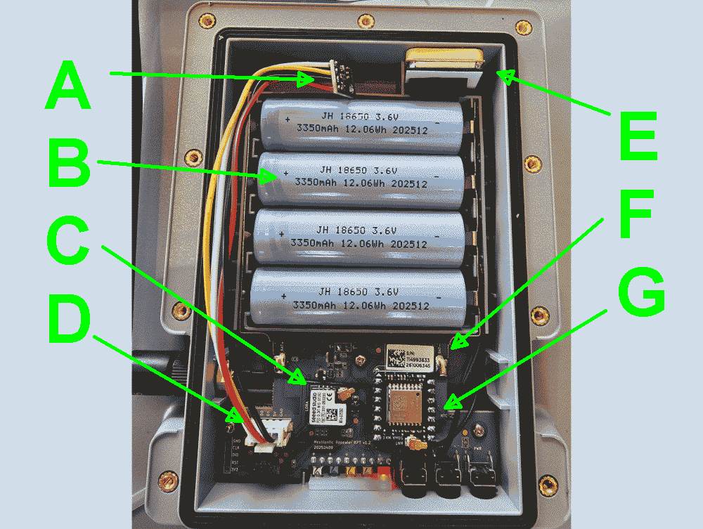
My next step was to open up the solar meshtastic node. You can see the battery B which is four 18650 cells, each 3350 mAh at 3.6 V. This provides around 48 watt-hours of energy. (They get charged up by a five-watt solar panel.) You can see the GNSS chip G which is an L76K GPS module, and its GNSS antenna E. You can see the Wio-SX1262 LoRa transceiver C. You can see the XIAO nRF52840 processor F. And, importantly for this discussion you can see the Grove port D. And you can see that I added the sensor A.
Having added the sensor A, I closed up the housing and powered up the node. I logged in at the administrative interface of the node and checked a couple of boxes to turn on “telemetry” mode for the data from this sensor. And I was delighted to see the temperature, humidity, and air pressure information as shown at the start of the article.
Any meshtastic user in the service area of this node can click on their meshtastic device to see the temperature, humidity, and barometric pressure inside the node.
Have you worked with meshtastic? Please post a comment below.
How can the sensor work if it is enclosed in the sealed interior of the SenseCAP device? You would think that barometric pressure and humidity cannot reach it.
Thank you for commenting. Yes this is a very good question. The housing of the device is well sealed, for example having a gasket to seal the rear cover of the enclosure.
Barometric pressure. I believe that despite all of this sealing, the barometric pressure would inevitably equalize as between the housing and the ambient atmosphere. So I think the reported air pressure number is worth paying attention to.
Temperature. So I think the reported temperature number is worth paying attention to. This is relevant for example given that during cold times of year, the device would likely get very cold and this could affect the battery performance.
Humidity. What remains to discuss is the humidity. Yes, I think you are quite right on this. There is no reason to think the humidity inside the enclosure would track with or equalize with the ambient humidity. So I think all we can say is that this sensor tells us the humidity inside the enclosure.
Again thank you for commenting.