
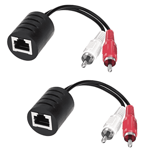
It is fun to learn about baluns. The word “balun” is a portmanteu (Wikipedia article) drawn from the words “balanced” and “unbalanced”. The idea of the balun (Wikipedia article) is to provide a way to connect a balanced electrical line and an unbalanced electrical line. I recently encountered the baluns that you see in the photograph at right, and I was pleasantly surprised to find that they really worked well despite falling far short of the classic defining qualities of a balun.
We start the discussion with a bit of review.
Unbalanced lines. The world of audio electronics is filled with unbalanced signal lines, typified by phono plugs and RCA plugs like the red and white plugs above. Each such line is usually a coaxial (shielded) cable. We think of the audio signal as passing through the center conductor and we think of the shield (outer) conductor as being largely passive, serving mostly as a way to define a common “signal ground” between two pieces of audio equipment and as a way to (hopefully) prevent external “noise” signals from reaching the center conductor. The audio signal would, one hopes, pass successfully from one piece of equipment to the next with little added noise and little loss of signal quality.
Those who have tried to get complicated systems to work correctly have often run into big problems where the supposedly common “signal grounds” or chassis grounds of various pieces of equipment are actively hostile to each other, and where it turns out to be a mistake to connect them to to each other with simple coaxial “unbalanced” cables like this.
We call it “unbalanced” because one of the two conductors (here, the shield) is very much tied to some external reference such as a chassis ground. Only the center conductor is free to assume various electrical values for the purpose of transmitting an audio signal.
In many audio systems, a typical amplitude for an RCA-cable line will be around 1 volt peak-to-peak. To the extent that some effort is made to define a characteristic impedance for the line, it might be a nominal 75 ohms across a nominal dynamic range of perhaps 20 hertz to 20 kilohertz. The coaxial cable used for an RCA-cable line is usually quite small in diameter, with quite a lot of capacitance per foot or per meter, and so it is rather “lossy”. For this reason, we usually limit such cables to maybe three feet or ten feet. In cases where it is desired to transmit an audio signal a long distance over a coaxial cable (for example to a subwoofer in a surround-sound system), one of the approaches is to use RG6 cable which is much less lossy.
Balanced lines. A much more elegant way to try to protect an audio signal line from induced noise is the use of a “balanced line”. The idea is that there are two conductors, neither of which gets tied to any external reference such as a ground. In a microphone, the two conductors would get connected to the capsule or transducer or coil that detects sound. At the other end, the two conductors would be connected to the two inputs of a differential amplifier. One aspect of the elegance of this approach is that any electromagnetic wave that strikes one of the conductors, perhaps tending to induce some electrical current in some direction (say, toward the microphone) will nearly identically strike the other of the conductors as well. When it does, it will tend to induce very nearly the exact same electrical current in the same direction (again toward the microphone, in our example). We can think of the two currents as smashing into each other and canceling each other out. The geek term for this is “common-mode rejection”, by which we mean that a potential source of electrical noise is likely to have a common effect on each of the two conductors, and this permits the balanced line to “reject” the would-be source of electrical noise.
A second aspect of the elegance of this approach is that by having the self-discipline to avoid tying either of the two conductors to any external reference such as a chassis ground, we avoid a wide range of bad things that might otherwise have happened if, say, the chassis grounds of two pieces of equipment had been in some way electrically hostile to each other.

Classic baluns. We now discuss the classic balun. The traditional notion of a balun, as mentioned above, is that it provides an interface between an unbalanced line and a balanced line. One of the requirements for the balun is to provide whatever electrical connectors are needed to match the connectors at the two communications lines. Where one of the lines is tied to a ground and the other is not, the balun needs to provide some way to permit the signal on the “balanced” side to “float” relative to ground. The usual way to accomplish this is by means of an audio transformer such as that shown above right. The windings of the transformer provide electrical isolation between the two lines, while providing audio coupling.
A further goal for any balun is, of course, to minimize any impedance mismatch along the way and in particular at this connection point. Impedance mismatches lead to reflections and signal losses.
The alert reader immediately realizes that while a suitably designed transformer can indeed provide the needed electrical isolation and may well minimize or nearly eliminate impedance mismatches, it will nonetheless harm the frequency response of the system. Any inductor inevitably passes higher frequencies less freely than lower frequencies, or to say this another way, there will be some amount of high-frequency rolloff. But if you are required to “float” the balanced line, isolating it from ground, then ya gotta do what ya gotta do, to use the technical term.
Category 5 cables. In the world of so-called “category 5 cables” which among other things are used for ethernet, yet another smart thing gets done, namely that in addition to employing “balanced lines” made up of two conductors each, the manufacturer of the cable also twists each pair of conductors. One can work out theoretically, and one can confirm experimentally, that twisting the conductors makes it even harder for any potential source of electrical interference to successfully inject noise signals into the line. (There are four pairs in a category 5 cable, and each pair is twisted at a different number of twists per inch or twists per centimeter than the other pairs. This greatly reduces the risk of crosstalk from one pair to another.)

XLR cables. In some balanced-line cables, an additional protective measure against noise is provided, namely the conductors that carry the signals are shielded by a shield that surrounds them. In the audio world, the most commonly encountered balanced-line audio cable is the so-called “XLR” cable which uses three-pin Amphenol connectors (Wikipedia article).
Back to our story. Having laid this background, I can turn to the odd “balun” devices shown at top right. The advertising claim for these devices is that they permit an RCA-cable type of audio signal to be passed a great distance over ordinary category 5 cable.
I needed to be able to pass a stereo audio signal from a preamplifier in one room to some power amplifiers in a different room that is about 100 feet away. The legacy approach for this would be to run a couple of RG6 coaxial cables between the two locations. In this particular situation, this would have been difficult, because the walls are closed up and it would be quite a challenge to fish the coaxial cables. I did, however, have an already-installed category-5 cable running directly between the two locations. So I decided to give this product a try. I placed an order for the baluns.
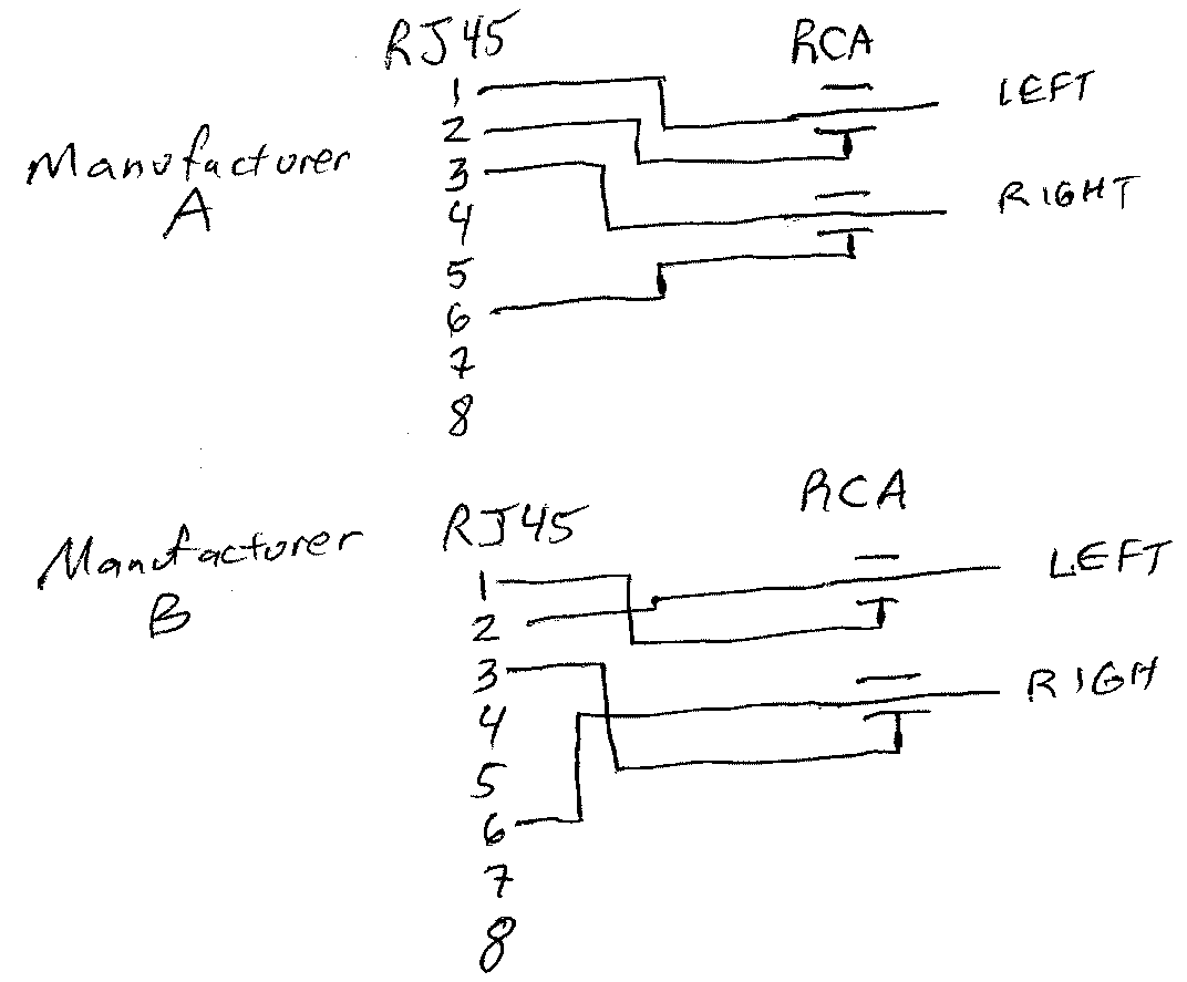
What I assumed is that when the baluns arrived, I would find that each balun contained a transformer like the one shown above. Nope. These devices are extremely simple. There is simply an ordinary metallic connection from the tip and shell of a first RCA plug to pins 1 and 2 of an RJ45 jack, and an ordinary metallic connection from the tip and shell of a second RCA plug to pins 3 and 6 of the RJ45 jack.
One might ask “why only 1, 2, 3 and 6?” and the answer of course is that there are some ethernet cables where these are the only conductors that are connected. Saying this differently, some ethernet cables simply do not have anything connected to pins 4, 5, 7 and 8.
Is “balun” even the right word for this? I guess broadly speaking we can say yes to that. The twisted pairs in the category 5 cable are definitely balanced lines. So yes this device is providing, in its own very crude way, an interface between a balanced line (a twisted pair in the cat 5 cable) and an unbalanced line (the RCA-plug audio signal line). But what jumps off the schematic is that no effort is being made to permit the balanced line to “float” relative to the chassis ground of the RCA plug. There is no electrical isolation that would permit “floating” of the balanced line. How can this possibly work? The answer of course, such as it is, is that we assume the user has control over both ends of the category 5 cable. A matching balun is being used at the other end of the category 5 cable. In this way, it sort of does not matter that the balanced line in the middle was deprived of its normal opportunity to “float” relative to a chassis ground or other external ground reference.
We also see that this run of category 5 cable is likely to have a noise rejection or noise immunity that is not so very different from that of an ordinary coaxial cable. It is a twisted-pair cable and it probably has a very robust common-mode noise rejection capability. We remind ourselves that the category 5 cable was designed to transmit signals at least as high in frequency as 350 megahertz with little or no crosstalk and little or no susceptibility to external sources of electrical interference. As such, it would not be such a surprise if this same cable could nearly effortlessly accomplish similar results for signals that are no more demanding than ordinary audio that only reaches 20 or 30 kilohertz.
We can also give a moment’s thought to signal loss per foot due to parasitic capacitance. The cat 5 cable is made with materials choices and geometries that permit signals to get from one end of a 100-meter cable to the other end all the way up to 350 megahertz or more. So it would not be such a surprise that the cat 5 cable will permit a mere 20-kilohertz signal to get from one end to the other with only a little capacitive loss.
What also leaps off the schematic, however, is the realization that probably no attention whatsoever has been paid to impedance matching. Who knows what the characteristic impedance is for category 5 cable when it is carrying audio signals? I certainly do not know the answer, but I have no particular reason to think it matches the nominal 75 ohms of audio-type RCA lines.
From an electrical engineering point of view, this product “cheats” shamelessly. No self-respecting electrical engineer would actively recommend this as a generally applicable way to transmit a high quality audio signal from one place to another, except in particular cases and then only as a sort of “try it and see”. Yes in some cases with some cables and with some pieces of equipment at the two ends of the cable, it might work well. But surely with some other cables, and with other pieces of equipment at the two ends of the cable, it might be disappointing or might not work well at all. Will impedance mismatches lead to signal losses? Will impedance mismatches lead to signal reflections? Will high audio frequencies get lost due to parasitic capacitances along the way? The only way to find out would be to try it and see.
What I found, and I am very critical listener, is that these baluns delivered on their promise. The audio signals were transmitted completely faithfully, with no high-frequency loss, and no induced noise from sources along the way. I think that for my combination of cable type and equipment types, these baluns provided exactly what I needed.
One must be careful to avoid getting a mistaken impression that the information is being passed from one balun to the other as, say, ethernet datagrams. These baluns will disappoint you if you try to connect them to ports on an ethernet switch. The connection between the two baluns needs to be a simple metallic connection.
We then get to the final gobsmack. I ordered two sets of these on Amazon, from two different vendors (“A” and “B” in the schematics above). The text product descriptions were identical, and the photographs were very close to identical. As you will see, however, the pin assignments are not identical. Vendor A chose to put the signal grounds on pins 2 and 6 (and the signals on pins 1 and 3). Vendor B chose to put the signal grounds on pins 1 and 3 (and the signals on pins 2 and 6).
Suppose I had gotten the baluns mixed up, as between the two vendors? The result would likely be a howling sixty-cycle hum or squeal on both audio channels. Chassis ground at one end would become the to-be-amplified signal at the other end, and vice versa. There is, of course, no industry standard for how to map RCA signal pins to RJ45 pins when you are “cheating” to use in-wall ethernet cabling as a proxy for RG6 cable (which is what is going on here). So we cannot blame either of these manufacturers for having made pin assignment choices that differ from the choices that the other manufacturer made. The point is that these baluns simply must be used in “matched pairs”.
What solutions have you used when you need to communicate RCA-type audio signals over great distances? Have you tried “ethernet baluns” like these? Please post a comment below.