
In the old days, a POTS (plain old telephone service) telephone, also sometimes called an “analog phone”, got its dial tone from a pair of copper wires that led to a telephone company central office. The distance between the telephone and the central office might be miles. The telephone company might have sophisticated equipment in the central office that can test for faults on the telephone line, such as spurious voltages or shorted connections.
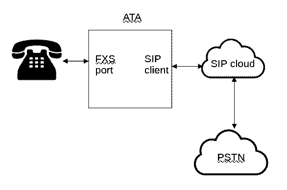
Nowadays if the customer is trendy, modern, and up-to-date, the POTS telephone will get its dial tone from an ATA (analog telephone adapter). At above right we see a functional blog diagram including an ATA. It turns out that some ATAs have sophisticated circuitry, like that in a legacy telephone company central office, that can test for faults on the telephone line, such as spurious voltages or shorted connections.
First we must establish some terminology. The ATA has a first port which is a SIP client, which registers a “SIP trunk” which connects to a SIP cloud provided by a VOIP telephone company. (The SIP trunk connects through the Internet, variously using UDP or TCP or TLS protocols.) The VOIP telephone company communicates with the legacy PSTN (public switched telephone network) so as to place and receive telephone calls.
The second port on the ATA is an FXS (foreign exchange subscriber) port. The FXS port, if properly implemented, replicates in all respects the function of the legacy telephone company central office. It is the FXS port that provides a dial tone if a user lifts the receiver of the POTS telephone, and receives dialed digits, and places a telephone call. It is the FXS port that receives an incoming telephone call through the SIP trunk, and causes the telephone to ring.
 A typical ATA appears at right. The ATA is a nearly featureless device, with no keyboard and no display screen. There are a few LEDs, a power jack, an ethernet jack, and an RJ11 telephone jack, and that’s all.
Which brings us to the point of this blog article. Completely by chance I learned just now that some ATAs have sophisticated circuitry that can test for faults on the telephone line, such as spurious voltages or shorted connections. In such an ATA, it is possible to “log in” remotely at the ATA and to carry out these sophisticated tests.
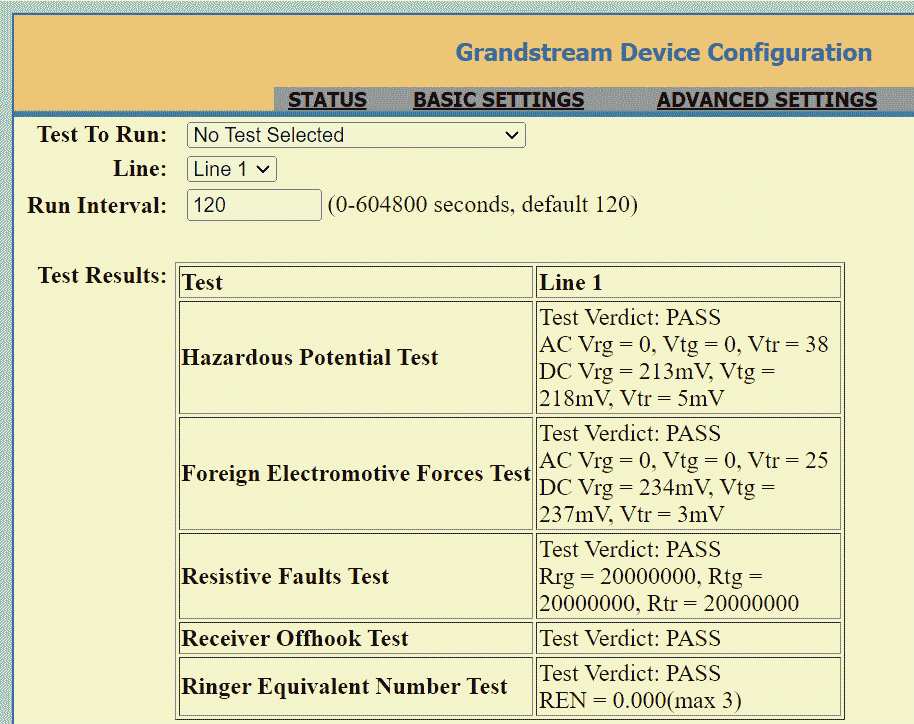
- At right you can see a screen shot of the results of a set of such tests. I clicked on a link captioned “GR909 test page” and then clicked a few more times. What I accomplished were:
- a Hazardous Potential Test,
- a Foreign Electromotive Forces Test,
- a Resistive Faults Test,
- a Receiver Off-hook Test, and
- a Ringer Equivalent Number Test.
These tests are carried out with respect to the two terminals of the RJ11 jack, which are called “ring” and “tip”.
Hazardous Potential Test. This tests for hazardous voltages on the FXS port. This includes:
-
- AC Vrg (alternating current voltage from ring to ground),
- AC Vtg (AC voltage from tip to ground),
- AC Vtr (AC voltage from tip to ring),
- DC Vrg (direct current voltage from ring to ground),
- DC Vtg (DC voltage from tip to ground), and
- DC Vtr (DC voltage from tip to ring).
You can see that in the test above, the results were a “PASS”. The voltages were all within tolerances.
Foreign Electromotive Forces Test. As far as I can see, this test is a duplicate of the Hazardous Potential Test.
Resistive Faults Test. This tests for shorts or near-shorts on the FXS port. This includes:
-
- Rrg (resistance from ring to ground),
- Rtg (resistance from tip to ground), and
- Rtr (resistance from tip to ring).
As you can see, each resistance was measured to be 20MΩ. I’d guess this is the maximum value that the testing circuitry is able to measure.
Receiver Off-hook Test. This tells us if a telephone receiver is off-hook, meaning a low resistance across tip and ring. As you can see, in this test there was no receiver off-hook.
Ringer Equivalent Number Test. This measures “ringer equivalence” meaning a standard impedance of a legacy telephone ringer at a standard ring frequency of 20 Hz. One legacy ringer often presented an impedance of around 7KΩ, so if this test finds 7KΩ at 20Hz then we say there is a “REN” (ringer equivalent number) of 1. If this test finds 3½KΩ at 20Hz then we say there is a “REN” (ringer equivalent number) of 2, and so on. As you can see, in this test the impedance was extremely high, so the REN was zero.
Why is it called “GR-909”? It turns out that these tests are defined in Telcordia standard GR-909, which you can purchase as a PDF file for $655. (Or you can read this blog article and you will not need to pay $655.)
The main point of all of this is that if you happened to have selected a sufficiently feature-rich ATA, such as the Grandstream HT801 ATA pictured above, you can do a GR909 test remotely. This may permit you to diagnose a problem or trouble condition remotely.
I invite the alert reader to join me in wondering how any of these parameters can be measured relative to “ground” given that an ATA generally has no connection to any “ground” or earth potential.
Have you used the GR-909 testing capability of an ATA? Please post a comment below.