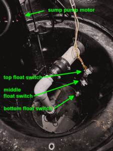
I decided to try to monitor a sump pit. This is how the project stands as of now.
This is a sump pit in a basement location that would hopefully always be dry. But the sump pit was set into place just to be on the safe side in case things were to get wet at some future time. My goal was to monitor the sump pit so as to learn of developments and problems.
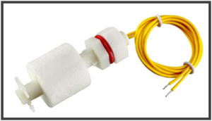
The starting point was to mount several float switches in the pit. The float switches cost $3 each. Each float switch has a float with a magnet cast into it. The float slides up and down on a vertical shaft. Inside the vertical shaft is a reed switch. This particular switch is constructed so that the reed switch is at the lower end of the shaft. Stated differently, the switch is “closed” (electrically conducting) when the liquid level is below the level of the float switch.
You can see the three float switches mounted in a side wall of the sump pit (photograph at top right). The bottom float switch is mounted as low as possible in the pit, so that it basically senses whether the pit is “empty” or “not empty”. The middle float switch is positioned in the middle of the tidal range for the sump pump, by which I mean that this switch should change its state every time the sump pump operates. The top float switch is located above the highest level of normal operation of the sump pump, so that if this switch opens, it is an indication that the sump pump has failed to operate as it should.
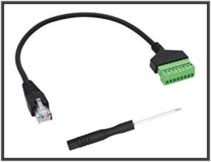
There is an ethernet jack positioned very nearby to the sump pit. I recently learned of the existence of a very convenient adapter (photo ar right) that provides a terminal block cable breakout for RJ45 jacks. This makes it very easy to repurpose an ethernet link for other purposes such as the sensors described here.
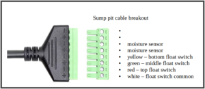
The adapters are used in pairs, a first adapter at the distal location (here, the sump pit) and a second adapter at the wire center.
At the wire center I chose to use a Xytronics X408 digital input module (image at right).
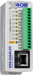
This module is part of an ecosystem of controllers that I find to be very convenient and reliable for home automation purposes. Within the module I defined some simple business process rules that you can see in the screen shot below.
A first rule sends an email if the previously empty sump pit gets enough water into the pit to trigger the bottom float switch. A second rule is hopefully never invoked, but it sends an email if the water level gets so high that it triggers the top float switch. This would presumably be due to a failure of the sump pump.
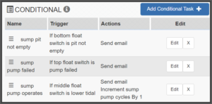
The third rule maintains a count of operational cycles of the sump pump. (The controller permits the user to define “registers” that can be used for various purposes such as maintaining a count of events.)
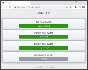
The controller has an embedded web site. One of the web pages displays configurable status information such as seen at right.
The ecosystem for these Xytronics controllers permits any of the controllers in the system to pass messages and status information in real time to other controllers in the system. In a typical setup, the controllers would all be on the same local area network on a non-routable (NAT) subnet. In this way, some second controller could (for example) be kept informed of events in this X408 controller, and could start a timer when the top float switch has been triggered, and after some predetermined timed interval could close a set of relay contacts to sound an audible alarm in the event of sump pump failure. The result could be that the audible alarm serves as an escalation in the event of my failing to respond promptly to an email alert that I had previously received.

You should also monitor your sump outlet periodically. In my previous house the sump ran all the way down a hill to a clump of trees. We were perplexed that the sump pump was constantly running, even in dry weather. We found the sump outlet in the course of another project and realized there were a bunch of tree roots obstructing the outlet pipe. We cleared out the pipe, the pump was finally able to empty the sump, and the problem was solved.
Thank you for posting. Yes if the homeowner is as alert as you were, the homeowner notices the run time of the sump pump being “forever” and this leads eventually to the discovery of the obstruction at the “daylight” of the drain line.
I have to imagine that for many homeowners who are less alert than you, the discovery path for such an obstruction would be quite different. The discovery path would be that the sump pump motor burns out, followed by the homeowner eventually learning that the sump pump is no longer doing its job. (In the system described in the blog article, this would hopefully be detected by the top float switch.) The typical way of the homeowner learning that the sump pump is no longer doing its job would be the realization that the basement is now ankle-deep in water.
Your main point I guess being that the “daylight” for the drain line would benefit from a periodic inspection.
Once again, thank you for posting.
Carl, if ever SHTF, you’ll probably be the only patent attorney among the survivors. I don’t think there are many that can do hands on stuff like this, and at this level. (No pun intended.)
Thank you for commenting. From time to time it has crossed my mind to think that if the S were to HTF, the people who know how to use a soldering iron to repair a broken flashlight, and who can do similar practical things, would be able to barter such skills for cans of tuna and penicillin pills and other things of value. I do think there are plenty of other good reasons to learn how do use a soldering iron and such, but maybe this is one more reason.
Those switches would have served me well when I had a non-submersible sump pump which came with the house, leaves jammed it in a pumping position, and the motor burned out.
I then bought a submersible sump pump and never had problems again.