
Readers will recall that I am slowly creeping in the direction of doing some ham radio transmitting.
It turns out that anybody who creeps in this direction sooner or later realizes that he or she is going to need a “dummy load” (Wikipedia article).
The idea of a dummy load is that if you are adjusting or testing your RF transmitter, it is considered impolite to do this by connecting the transmitter up to an actual antenna. Layered on top of this is the likelihood that the actual antenna will fail at its goal of having ideal impedance at the particular radio frequency being used in the test. (The geek-speak way to say this is that the antenna will provide an SWR of some value other than 1:1.)
So what you want to do, so as to avoid being impolite, is to connect the transmitter up to a so-called dummy load. In the world of RF, the design goals for a dummy load include:
- It should have an impedance of the correct value, at the transmitting frequency of interest. In the world of ham radio that value is “50 ohms”.
- It should be able to dissipate some amount of power (expressed in watts), more or less continuously for the duration of the desired testing period, without burning up or deviating from the desired impedance.
- It should not cost too much money.
- It should be neither capacitive nor inductive. It should present a pure resistance with no “imaginary” component to its impedance.
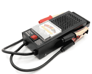 The other place where dummy loads arise in the everyday life of a reader of this blog is, of course, the testing of a 12-volt car battery. The grilled area at the upper right portion of this tester contains a bunch of toaster wire (nichrome wire) sized to be about 0.12Ω in resistance. The idea is that when you flip the spring-loaded switch into the “on” position, the resistor is connected to the battery clamps (and thus to the battery under test). From Ohm’s law we can work out that about 100 amperes will be flowing, which is intended to simulate the load of a car starter motor. If you peek through the grill during the test, you see the nichrome wires turning bright red, and 1.2 KW of power are developed. A simple d’Arsonval (Wikipedia article) meter movement permits the user to see what voltage is being provided to the dummy load. The main goal is to work out an estimate of the ESR (equivalent series resistance, Wikipedia article) that is inside the battery. If the ESR is extremely close to zero, then the meter says the voltage is close to 12 volts and this means that battery is healthy. If the ESR is nonzero, for example if it is 0.12Ω, then the meter says the voltage is maybe 6 volts and this means that battery is shot.
Returning to the discussion of RF dummy loads. When I was a teenager, a typical way to obtain a ham radio dummy load was to construct it yourself. You would string together a number of so-called “carbon resistors” into an array that comes close to 50 ohms in resistance and has the desired wattage rating. You would then mount this inside a used paint can, and fill the can with some type of oil, typically mineral oil which will hopefully not go rancid the way vegetable oil probably would.
I say “carbon resistors” because what you absolutely do not want to use is so-called “wirewound” resistors. Such resistors have a substantial impedance component due to the wire forming a coil.
The home-made dummy load was called a “cantenna” because it is an antenna in a can. The can provides RF shielding, and the oil provides some amount of thermal mass. Hopefully by the time you finish your testing, the oil has not yet been brought to a boil.
Nowadays you can make a mail-order purchase of a very handy dummy load for a cheap price. This saves the ham from having to go to the trouble of constructing it, which risks spilling a gallon of mineral oil inside the house.
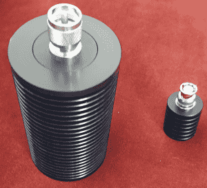
At the left side, in the photograph above, is a 100-watt dummy load rated for frequencies from DC (direct current) up to 520 MHz. The one on the right is a 10-watt dummy load rated for frequencies from DC up to 3 GHz. Each of these dummy loads promises an SWR that is no worse than 1.2 to 1.
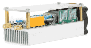 The alert reader will be asking, why is a 10-watt dummy load not enough? The transceiver that I purchased (previous article) is a QRP device, generating at most about 10 watts of RF power. The answer is that if all goes well, eventually I will also have a 100-watt linear RF amplifier, shown at right. It will thus require a 100-watt dummy load for testing and configuration.
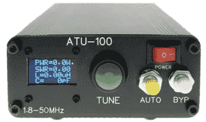 The alert reader will also recall that I had purchased an antenna tuner, seen at right. The good news is that this tuner is rated for 100 watts of RF power. It is designed to do antenna tuning over a range of 1.8 MHz to 50 MHz. This embraces the following ham radio bands:
- 160 meters
- 80 meters
- 40 meters
- 30 meters
- 20 meters
- 17 meters
- 15 meters
- 12 meters
- 10 meters
- 6 meters