

I realized that for quite a long time, I had sort of wondered how the tire pressure gauges work that have a thing that pops out. Clicking around on the Internet, I have now learned what the common name is for that kind of tire pressure gauge. It is called a “pencil gauge”. And I have learned how they work.
 Here you can see a cross section.
The pencil gauge has a piston (brass colored in the image) that can move from left to right in the image. There is a spring that urges the piston toward a rest position at left in the image. The sliding from left to right of the piston happens within a cylindrical tube.
The next thing to describe is an indicator rod. It has the white cap in the image. The indicator rod is more or less free-floating relative to all of the things that are around it. Among other things, if you were to grab the exposed tip of the indicator rod (its right end in the image) and pull on it, you could pull almost all of the indicator rod out into the open. At this point we realize why the white cap is as big as it is. The white cap is so big so that the indicator rod does not come all of the way out and get lost or something.
So now we can talk about what happens when you push the gauge onto the tire. A little bit of air flows out of the tire and eventually there is a steady-state condition where the pressure within the gauge (between the blue thing and the brass colored piston) matches the pressure within the tire. So this does not depend on any “rush” of air coming out of the tire. The air could come out of the tire as fast or as slow as one might wish — it is only that eventually a balance is reached with identical pressure in each of two places. The two places, again, being a first place within the gauge, between the blue and brass things, and a second place being the interior of the tire.
During this period of time during which there is this steady-state condition of pressure in the two places, there is a tendency for the air pressure to urge the piston to the right in the image. This means the piston is being urged that way, against the pressure of the spring. It is recalled that the behavior of the spring is modeled according to Hooke’s law, meaning that we assume that it squeezes more or less linearly in response to force. So what we expect is that during this steady-state period of time, a period of time during which the pressure within the main body of the gauge is the same as the pressure within the tire, the piston moves to the right in the image by some distance that is linearly related to the air pressure. This pushes the indicator rod out into the open by that same distance.
Then an interesting thing can happen. We can pull the gauge away from the tire, at which point the air pressure flows out of the gauge and the spring urges the piston back to its rest position which is to the left in the image. Now of course if we were somehow to use our X-ray eyes to look to see where the piston is now, its location would no longer tell us anything about what the tire pressure was (and is). But the fun part is, the indicator rod is out in the open, and it protrudes by an amount that is linearly related to the tire pressure. Markings on the rod permit us to read a number that tells us the tire pressure. Then when we are pretty sure that we did successfully read the number and committed it to memory, we can push on the indicator rod and get it back into its rest position within the gauge.
Of course for this whole thing to work, several things have to be just right. If anything of these things are not just right, then the gauge would fail to give a correct answer about the tire pressure.
-
- Fairly good air seal between the piston and the cylinder. The seal has to be a Goldilocks seal. If it is too leaky, then this might lead to the gauge failing to register all of the tire pressure because of air leaking past the piston, and the gauge might read too low. But the seal cannot be too good. If the seal is too good, then maybe the piston might fail to go as far to the right as it should, because of friction with the cylinder. So it has to be “just right”.
- Friction. Tied to the requirement that the air seal be “just right” is the friction that was just mentioned. If there were too much friction between the piston and the cylinder, then there are actually two things that could go wrong. Yes, the piston might fail to go as far to the right as it should, leading to a too-low reading on the gauge. But another thing that could go wrong is the piston not returning all the way to its home position when we are done using the gauge.
- Another Goldilocks requirement. The indicator rod and its white cap need to be very light in weight so that their mass does not make things sluggish. And their relationship with the things around them needs to be very nearly friction free. But wait! It cannot be completely friction free because we want the indicator rod to stay where it is when it is indicating the pressure. So this amount of friction between the indicator rod and its surroundings needs to be a Goldilocks amount of friction. Not too much friction, not too little, but “just right”.
- Potential contaminants. There is also the fact that this whole mechanical design can get thrown off if any contaminant gets into the cylinder, like dust or dirt or oil. A moment’s reflection reveals that there are not one but two entrance paths for such contaminants.
- First contaminant entry path. Every individual measurement cycle with the gauge introduces some nonzero amount of high-pressure air into the gauge, and each such volume of air might have dust or dirt in it. Suppose for example that the valve stem of the tire had a bit of mud or dirt in the opening, and we press this gauge into place on the valve stem. As the night follows the day, this will blow some of that mud or dirt into the body of the gauge. This mud or dirt can then get into the Goldilocks clearance between the piston and the cylinder. This could throw off one individual reading. But this could also lead to erosion of the smooth inner face of the cylinder, or the smooth outer face of the piston, and the erosion could throw off future readings.
- Second contaminant entry path. Every individual measurement cycle with the gauge leads to some period of time during which the indicator rod is out in the open. It might remain out in the open for some number of minutes or longer, until the human user decides to push on the indicator rod to get it back to its home position. During the time that the indicator rod is out in the open, it cannot be ruled out that it might get oil or water or mud on it. Later when the rod is pushed home, the contaminant can end up in the cylinder, deposited on the smooth inner face of the cylinder. This could throw off the next individual reading or could lead to erosion of the piston and cylinder. Or could lead to stickiness or friction for the piston, or could corrode the spring.
- End point inaccuracy. If we use a graph to describe the observed physical movement of the indicator rod as it relates to the tire pressure, we can make a guess that it will be pretty close to a straight line (Hooke’s law as mentioned earlier). And pretty likely Hooke’s law will work. Most real-life springs really do behave linearly within some fairly predictable range of motion. It is a straightforward matter to design a physical thing like a scale or pressure gauge so that the spring involved never gets deformed, in normal use, past its linear range. But what about end points? This is like asking “on the graph, does the line pass through the X-Y origin?” With a spring scale, it is easy to provide a little adjustment knob to make it so that the needle points to zero at a time when the weighing pan is empty. But with this pencil gauge, I do not see any natural way that the human user would have any opportunity to somehow “correct for zero”. So it seems to me that the lack of a way to correct for zero is a source of potential measurement error that cannot be ignored.
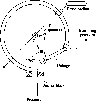
We can compare this with the old-fashioned Bourdon tube gauge (Wikipedia article).
The Bourdon tube gauge has no contaminant entry path from outside the gauge (like the path at the indicator rod). And if a contaminant were to enter the tube, from the tire, it would have little or no opportunity to cause trouble. It would probably merely rattle around or float around harmlessly within the tube.
Yes the Bourdon tube gauge has possible failure modes and has ways that it might fail to be accurate. The Bourdon tube gauges that I like best are the ones that are filled with a clear oil. The clear oil tends to keep crud away from the moving parts such as the linkage and pivot and rack and pinion, and it lubricates the gear teeth.
It is only within recent years that I have frequently found myself paying attention not so much to “what are the failure modes?” for some device or apparatus, or “what is the likelihood of failure?” for that device or apparatus, but instead to “to what extent is the design of the thing likely to lead to the user figuring out promptly and unmistakably that a failure happened?”
While writing this lengthy essay, I realized that there are actually some reasons to think the pencil gauge might rank better on this latter metric than the Boudon gauge. With the pencil gauge, the alert user might well notice right away if the indicator rod failed to pop out at all, as expected, or if the indicator rod sort of crept out into place instead of popping out fast. So the failure modes involving friction and crud in the cylinder have some opportunity to get noticed. Not only that, but the very act of smacking the indicator rod back home might actually sometimes have the good luck to provide a salutary “self-cleaning” result for any crud or dust that had found its way into the cylinder.
In contrast, with the Bourdon gauge, if crud or corrosion that were to lock up the gear teeth, this might happen at a time when nobody is looking at the gauge. The indicator needle might get stuck in place but there might be nothing about this that catches the attention of the human observer. Days or weeks might pass during which the human observer glances at the needle, sees that it looks normal, and then moves on to some other activity.
There are of course those times when the human user taps on the gauge, just to break it loose if somehow it had gotten stuck. But for this to make a difference about things, the human user needs to have somehow gotten the idea that tapping was called for.
Comments are welcomed.
I’ve used the pencil gauge many times this week with the new snowtires. They were over inflated by the shop.
I much prefer the pencil gauge that only has one opening and a “ball” end vs the two-sided ones which are fussy about getting it settled exactly on the tire valve. And now, having ready your post, I see the two-way gauge has two ways to be contaminated or plugged up.
My experience with pencil gauges is that for accuracy the indicator rod needs to be pointed up, so that gravity and momentum do not push-pull the indicator rod further out of the tube. The challenge is reading the scales upside down while holding the gauge in place. I think the inaccuracy when pointed down is because after a few years, the plastic bushing at the end of the tube wears out so that the friction no longer sufficiently holds the indicator rod in the correct extended position. But, I like my new digital read-out tire gauge with a backlit dial. Even better are the TPMS sensors with a dashboard tire pressure read out. Before the gauges were invented, is this what “kicking the tires” was for?
Hmm, interesting note about failure modes. I’ve got a pencil style gauge and a Bourdon style gauge for my tires, and I’ve noticed that (despite what I initially guessed) the pencil gauge is far more consistent. I can get readings to within a 5psi range every time. With my Bourdon gauge, it’ll often be off by 10 or 20 psi, for no apparent reason, making it useless for tires.
A direct drive gauge has a Bourdon tube, but it is in a spiral or a helical (corkscrew) formation instead of the traditional C shape.
The digital one seem to be very accurate, but I wonder about how long the battery will last if I leave it in my car so I’m looking at the pencil types. But they, especially the cheap freebies, seem like they weren’t very accurate. I searched a bit and some of the better made in USA pencils supposedly are pretty accurate, but I wonder a few things. Do the pencil gauges ever need a lube sprayed in them to keep the piston sealing? If you use a stop leak like Slime in your ties will that affect pencil and other types of air gauges? Will the piston degrade in the heat of the car and affect accuracy? Thanks for the explanation on how they work!