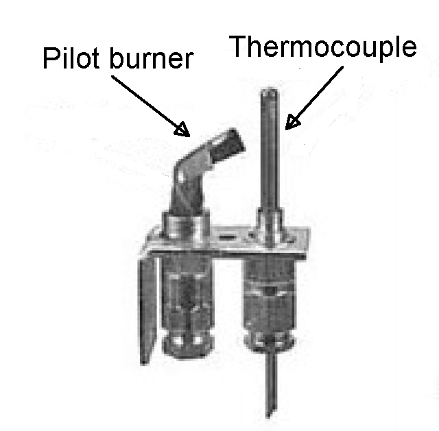
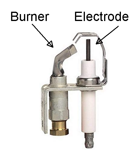
| before |  |
| after |  |
The problem was that the pilot light in my boiler kept blowing out. This blog article describes how I managed to fix that problem.
Many water heaters, furnaces, and boilers are gas-fired. The concern, of course, is to avoid an accumulation of unburned natural gas (or propane) in a living area. Such an accumulation would be a fire hazard if a spark or other flame were to ignite the accumulation of unburned gas.
The protective mechanism that I recall from the days of my youth (many decades ago) was to use a thermocouple. A rather sophisticated gas valve (omitted from the photograph) would refuse to turn on a large gas flow to a main burner unless the thermocouple indicated that there was flame present on a small burner (the pilot).
When you “light a pilot light” there is always a pushbutton that you push and hold while you are lighting the pilot light. This compresses a spring of a sort of mousetrap mechanism. When you get the pilot light lit, you wait a little while as the thermocouple heats up. When the thermocouple gets hot enough, it generates some electricity which powers a latch in the mousetrap mechanism. The latch keeps the mousetrap from triggering.
In the event that the pilot light goes out, the thermocouple cools and stops generating electricity. This releases the latch of mousetrap mechanism. The spring of the mousetrap mechanism causes the mousetrap mechanism to activate. This cuts off the small gas flow to the pilot burner. The same mousetrap mechanism also denies any gas flow to the main burner.
In this way, when the pilot light goes out, the total amount of unburned gas that escapes into the living area is quite small, and the escape lasts only for a few seconds.
This is great, except that when the pilot light goes out, somebody has to relight the pilot light. This person has to go in person to the water heater or furnace or boiler, and has to carry out the many steps required for relighting the pilot light. This involves closing a main gas valve, removing an access panel, lighting a match, pushing the pushbutton, applying the match, waiting a while, and then releasing the pushbutton. Assuming that the thermocouple has successfully powered the tiny latch inside the mousetrap mechanism, then the pilot light will stay lit. The user can then reassemble the access panel and reopen the main gas valve. There is a then a very satisfying “whoosh” as the main burner bursts into flame and starts warming up the very cold house.
A typical failure mode in my home was that a gust of wind could blow down the flue and blow out the pilot light. This would happen once or twice during a winter, on a day of high winds. This would invariably happen on a day when I was traveling. So the boiler (and the house) would get cold and stay cold until I were to return from my travels.
It turns out that Honeywell makes a retrofit kit that permits retrofitting an electronic spark ignition to such a boiler or furnace. You remove the old burner assembly (shown above) and install a new burner assembly (also shown above). You remove the old gas control valve and replace it with a fancier gas control valve. You add an “ignition module” which is a pretty sophisticated bit of electronics as I will discuss below.
As you can see in the picture, the new burner assembly has a sort of spark plug (they call it an electrode). When there is a call for heat, the call goes to the ignition module. The ignition module tells the gas valve to permit a small flow of gas to go to the burner. The ignition module sends high-voltage pulses of electricity to the electrode, which of course makes a series of sparks from the electrode to the chassis. Assuming all goes well, the sparks ignite the gas at the pilot burner.
Here’s the fun part. The ignition module measures the electrical conductivity in the spark gap (the region of space between the electrode and the chassis). In the absence of any flame, the conductivity is very low. (Air does not conduct electricity very well.) But if there is a flame, well, it turns out that an active flame contains lots of ions that conduct electricity.
The sparks are about once every 300 milliseconds. The ignition module carries out the conductivity measurement in the intervals between the sparks. So the ignition module generates a high voltage and sends it to the electrode (creating a spark), and then a few milliseconds later the ignition module attempts to pass a smaller current through the spark gap, and measures the amount of current, and works out whether there is a flame present in the spark gap. Then if there is no flame yet, the ignition module stops trying to measure the conductivity of the air, and generates another pulse of high voltage, thus sending another spark, and so on.
Eventually if all goes well, the burner lights. Then when the ignition module decides that the pilot burner has been going for a long enough time, it instructs the gas valve to permit a large flow of gas to the main burner (of the boiler or furnace).
During the time that gas is flowing, the ignition module repeatedly carries out the conductivity measurement to make sure that the flame is still going. If (presumably this does not happen very often) the flame goes out, then the module tells the gas valve to shut off the gas flow to the pilot burner and to the main burner. The module permits some time to pass (so that any unburned gas that escaped into the living space could dissipate) and then tries to light the pilot burner and main burner again.
In this way, the amount of unburned gas escaping into the living area (in the rare instance of the flames going out) is quite small and the escape does not last very long.
I imagine that this system which multiplexes the electrode (sometimes used for sparks, and at other times used for conductivity measurement) was patented by Honeywell. And I imagine the patent has long since expired.
The chief advantage of this system from my own selfish point of view is that I no longer have to worry about having to relight the pilot light. The pilot light would presumably almost never blow out since nearly always when the pilot light is going, the main burner is also going. No gust of wind down the flue would be able to blow out the main burner! In the rare instance of a gust of wind down the flue might happen to arrive at the exact time that a sparking activity is going on to light the pilot light, the ignition module is smart enough to try again a few seconds later.
No more returning from an out-of-town trip to a cold house.
A second advantage of this spark ignition system is that it saves gas. The pilot light is not always on (all through the spring and summer and autumn for example). Instead, the pilot light is only on when it needs to be on for the purposes of lighting the main burner. This should reduce my gas bill.
Maybe you are familiar with the Honeywell patent on this multiplexed burner electrode? Maybe you know the patent number? If so, please post it in a comment below. The first person to post the patent number in a comment will win a Camhatch.

I think this is the system of US 3902839.
Thank you for posting! I looked at this patent. My best guess is this is not the Honeywell patent on this multiplexed burner electrode. Several things make me feel this way. For one thing, the sparking circuit in this patent shoots a spark once per AC cycle (50 or 60 Hz). Meaning the spark comes about once per 16 milliseconds. In contrast, as I described, the system that I installed seems to spark about once per 300 ms. Another thing is that the system of this patent seems to rely upon the use of a first electrode (actually two, items 12 and 13) for sparking and a second (actually third) electrode (item 31) for flame sensing. In other words there seems to be no multiplexing of a single electrode. I will be sending a Camhatch to Mr. Fieschko, but I am counting this quest as still being open. I will be tickled if someone can find the Honeywell patent on the system that I described and installed.
One version of the spark control circuitry you described is in U.S. Pat. No. 3,377,125. Some adjustments to the disclosed components could provide the 300 ms spark cycle. This patent refers to, but does not describe, the main gas control module that turns the spark control circuitry on-off.
Thank you for posting! Yes the system of this patent surely does multiplex the single electrode. It gets used for sparking (to light the pilot flame) and for sensing (to detect the pilot flame). You are right that the components could be fiddled with to get the 300 ms spark cycle. It made me smile to see the designer’s choice of a neon bulb as the threshold device to trigger the pulse to the spark coil. Nowadays I think most designers would use some solid-state device as the threshold device, or would skip the thresholding completely and simply set a timer in software to determine the time to send the pulse to the spark coil.
I don’t really see where the designer was thinking about the safety requirement of shutting off the main gas valve in the event of flame loss. It sure looks to me as though the designer was only focused on figuring out when to stop the sparking (namely, stopping the sparking when the flame is detected).
Mr. Richards will also receive a Camhatch. But I am still going to count this as quest that is still open. I’m still interested to see if someone finds a Honeywell patent that shows the multiplexed electrode and, if flame loss is detected, shutting off both gas valves (the pilot gas valve and the main burner gas valve) and then cycling to try again with relighting the pilot light.
When I installed two new boilers, I specified electronic ignition. Saved a lot of pilot light gas, but the one spare part I bought was an electronic ignition module. I was told that this was the most likely part to fail. I have two seventy plus year old water heaters and the gas valves with pilot lights (I have never replaced them) are still working. I have replaced the thermocouples.
The ignition module is $89. Yes I have a spare module myself.
Great post. Thanks for sharing this post with readers. It was very interesting and helpful.