
Readers of this blog are already aware that I enjoyed the movie Glass Onion (blog article), from writer/director Rian Johnson. At about the time that Glass Onion became available for streaming, it came out that Johnson had just gotten done creating, writing, and directing a ten-episode television series Poker Face (Wikipedia article). I have greatly enjoyed all five episodes of Poker Face that have aired thus far.
Which brings us to episode four of Poker Face, entitled Rest in Metal. This episode has a plot element called a “Death Capacitor”. Which is what I will now discuss.
To appreciate death capacitors fully, it is necessary to recall that in the 1960’s, most electrical receptacles in the US had two slots that were the same size. (In present-day receptacles, one slot is longer than the other, and of course nowadays there is also always a third opening for a ground contact.) Back in the 1960’s an electrical appliance would have a power plug with two prongs (not three) and the two prongs were the same size. From this it follows automatically that the user could insert the plug either of two ways into the receptacle.
Nearly all consumer electronic devices that were made in the 1960’s have, of course, long since been taken out of service. Most have gone to scrap heaps and a handful can be seen in museums. But there is one specific and narrow category of consumer electronic devices that were made in the 1960s that are still in use in the present day, more than half a century after they were manufactured. What we are talking about is audio amplifiers that were made in the 1960s that use vacuum tubes instead of solid-state components. (Speakers of British English call vacuum tubes “valves”.) There is a subculture of guitar players who feel very strongly that it is better to use a tube-type amplifier than a solid-state amplifier. There is also a subculture of audiophiles who likewise feel very strongly that, for example, an audio preamplifier that uses one or more vacuum tubes for amplification is superior to one that uses solid-state components.
An audiophile explaining why he or she prefers the tube-type preamp will often describe a “warmth” or a “British sound” in the quality of the audio signal that passes from the preamp to the power amp, and from there to the speakers.
A guitar player explaining why he or she prefers, say, a Fender or Marshall or Vox guitar amp from the 1960s might describe how the tubes handle higher-than-rated electrical audio inputs. Yes, while many electrical engineers in many fields go out of their way to try to drive a component only with an input that is comfortably within its “linear range”, in the world of electric guitars in the 1960s, it was commonplace to intentionally “overdrive” the input of an amplifier. In many fields of electrical engineering it is more or less assumed that it is a shared goal to minimize or eliminate distortion and any driving of an active circuit element outside of its “linear range”. But in the world of electric guitars in the 1960s, there were many musicians for whom distortion was a feature, not a bug. It was a result to be pursued, not avoided.
And maybe it will not surprise the alert reader when I say that when you overdrive an audio amplifier, the distortion that results will be different depending on whether that amplifier is a tube-type amp or (for example) a solid-state amp (using transistors or integrated circuits).
The audiophiles who wish to have the “warmth” of vacuum tubes in their preamplifiers do not necessarily have to seek out preamps from the 1960s to get what they want, because in the present day there are dozens of companies who make high-end audio gear with vacuum tubes. But guitar players who want the distinctive distortion effects that were first heard in the 1960s often seek out original tube-type guitar amps from the 1960s and use those amps in the present day.
We are slowly creeping back toward episode four of Poker Face. The scriptwriter for this episode drew upon the fact that even now in the 2020s there are many guitar players who very loyally continue to use tube-type guitar amplifiers that were made in the 1960s. Some of those amps are in museums now, some have (regrettably) gone to scrap heaps, but a surprisingly large number of Fender, Marshall, and Vox tube-type guitar amplifiers from the 1960s are still in use right now. There are just a few more things that must be described about 1960s guitar amps and then we can return to episode four of Poker Face.
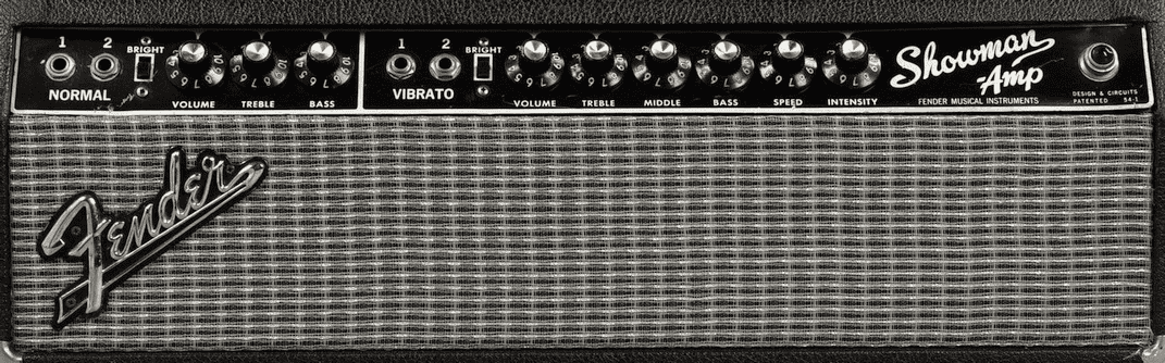
When the Fender Showman guitar amp (seen at top right) was released in 1960, it necessarily had a two-prong electrical plug. I say “necessarily” because in 1960, it was unheard-of for an electrical receptacle to be a three-conductor grounded receptacle. Not only that, but the receptacle did not even distinguish between the “hot” and “neutral” wires the way receptacles do nowadays with longer and shorter slots. In the 1960s, as I described above, the two slots were the same length. To put this into colloquial terms, if you were to approach a particular electric outlet, it was anybody’s guess which slot in that outlet was the “neutral” and which was the “hot” slot.
For many electrical appliances in the 1960s, such as a table lamp or toaster, you probably would not care which slot was “neutral” and which was “hot”, because the day-to-day operation of that table lamp or toaster would be the same no matter which way its plug got inserted into the outlet. But for the designer or user a guitar amp, this question of which slot was “neutral” and which was “hot” was of great interest. The reason for this great interest is that the amp had an electrical “chassis” which was intended to serve many electrical purposes simultaneously. The chassis would serve as a DC power ground for the vacuum tubes (with, for example, a 345-volt plate excitation voltage), and would serve as a signal ground for the audio path through the amplifier. This chassis was, necessarily, connected electrically to the guitar itself, through the “shield” conductor of the audio cable that connected the guitar to the amp.
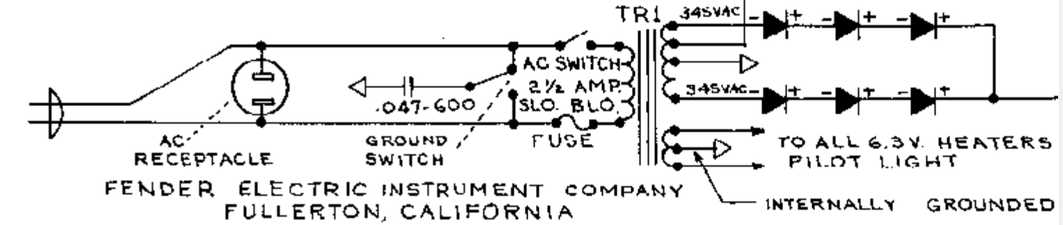
At right you can see part of the electrical schematic for the Fender Showman guitar amp. 120 volts AC enters the amp at left through the (unpolarized) power cord. A convenience receptacle was provided on the back of the amp so that another piece of equipment could be powered. (In this way the amp served as a sort of extension cord.) Following the AC power to the right in the schematic we see a power switch and a power-line fuse which feed the AC power to a power transformer. A center-tapped first winding on the power transformer provides 6.3 volts AC for the filaments (heaters) of the vacuum tubes, with the center tap tied to the chassis. A second winding, also center-tapped, provides high-voltage AC which, after rectification, becomes the 345-volt plate excitation voltage mentioned above. (That winding also provides other DC voltages for use elsewhere in the amp.)
The alert reader notices that the incoming AC power also reaches what is labeled as “ground switch”. This switch connects a 0.047 μF (microfarad) capacitor from the chassis to one or the other of the incoming AC power wires.
This, dear reader, is the Death Capacitor.
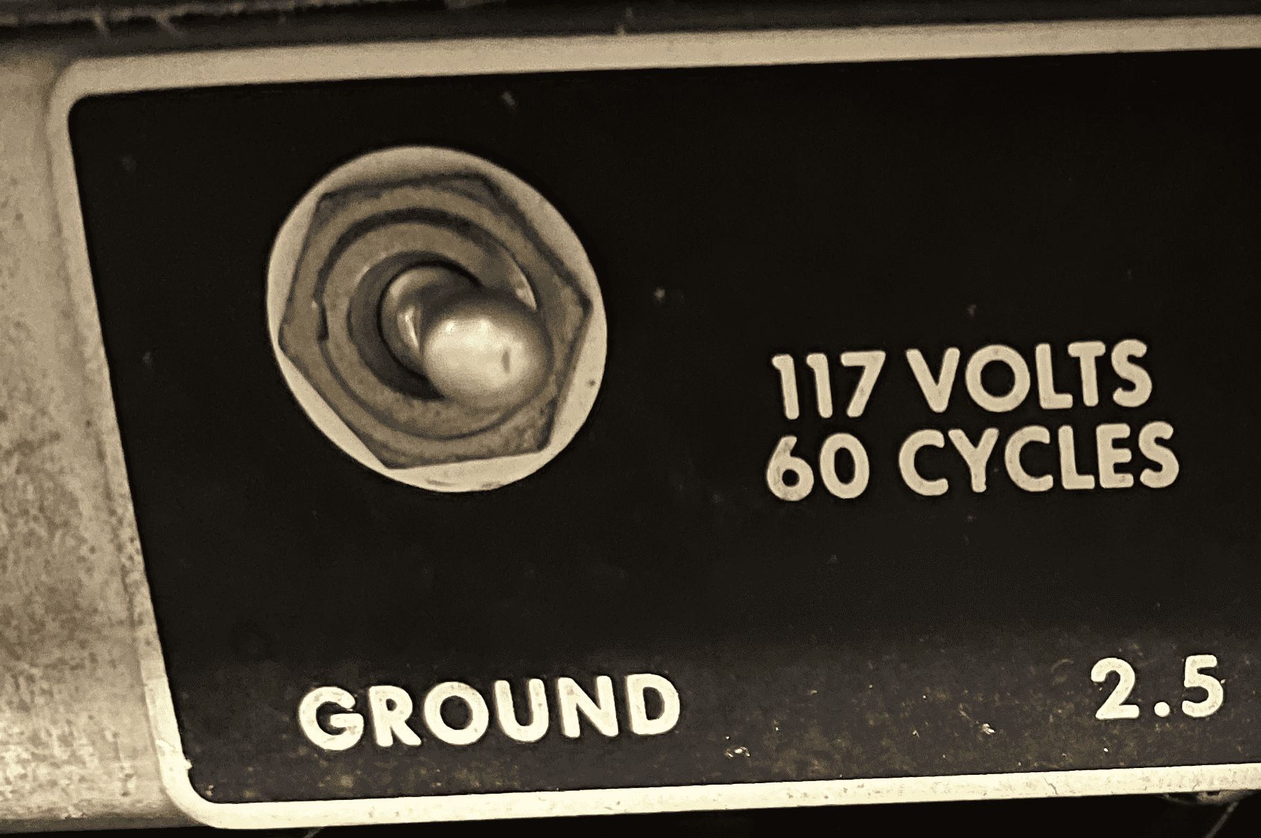
The ground switch on the Fender Showman is shown in the photograph at right. The idea is that when you are setting up your amp in a new location, you will plug it in to an electrical outlet, and then you do an experiment. You connect your guitar to the amp, power up the amp, and try flipping this ground switch back and forth to see which position generates less “hum” in the speakers. And indeed as a general matter, one position or the other will probably be quieter. If the “ground switch” is in the position that connects the “hot” wire of the power cord to the capacitor, this will inject a sixty-cycle hum into the chassis and probably into the entire amplification path. On the other hand, if the “ground switch” is in the position that connects the “neutral” wire to the capacitor, this offers a chance for any stray audio noise signals that are in the chassis to bleed off through the capacitor into the neutral wire and thence to an electrical ground.
The alert reader will already have done a quick bit of mental math and will have worked out that a 0.047 μF capacitor at 60 Hertz is roughly equivalent to a 56KΩ resistor. This means that if the “ground switch” is in the “hot” position, the hapless guitarist who is touching an earth ground and who touches the strings or pickup of the guitar might feel a tickle from as much as two milliamperes of AC current.
A modern-day GFCI (ground-fault circuit interrupter) will typically trip at about 5 mA, which tells us that the amount of current required to kill somebody must be a number bigger than 5 mA. And we note that 2 is smaller than 5. So the consequence of “getting it wrong” with the “ground switch” is, we guess, unlikely to result in death. Unlikely, that is, until such time as there is an electrical failure of said capacitor. The capacitor could “fail open”, or there could be the very bad luck of the capacitor failing in the direction of an electrical short. And now we have identified what could be a Death Capacitor. If the capacitor fails as a short or a near-short, and if the “ground switch” were to be in the position that connects the capacitor to the hot wire, then the chassis (and the guitar) could become an electrocution risk.
One of the members of this community of guitar players who very loyally make use of 1960s-era tube-type guitar amps is a good friend, and I learned from him that there is a smart thing that lots of the members of this community have done with their amps. They modify the guitar amp, swapping out the two-wire power cord for a three-wire power cord. (The “death capacitor” gets removed from the amp.) And they make sure to plug this power cord into a three-prong receptacle that has been tested to make sure that it has a real ground. In this way the chassis gets grounded to a true earth ground.
This modification has both advantages and disadvantages compared to the legacy situation of a death capacitor and a “ground switch”. The chief advantage of this mod is that with the chassis reliably bonded to an earth ground, the risk of electrical shock is greatly reduced. The chance of picking up the 2-milliamp tickle current is eliminated. But the permanent grounding of the chassis can lead to “ground loops” through audio cables connected to other pieces of audio equipment that might also have chassis with various non-identical relationships to an earth ground.
We can now “bring it on home”, just as a player of 12-bar blues might do in the last four bars of the progression. The delightful plot conceit of Poker Face is that each episode has a murder and of course the murder must be solved and dealt with. But Poker Face is not a “whodunnit”, where we the viewers try to guess who did it and eventually one or more “reveals” let us know who did it. No, Poker Face is set up not as a “whodunnit” but as a “howcatchem”. It evokes the old Columbo television series, where the episodic formula runs like this: the murder happens in the plain view of the television audience. We all know who did it. In the second act, the protagonist enters and realizes that there is a murder to be solved. We, the viewers, get to watch as the protagonist investigates and eventually works it out. And in the case of Poker Face, we have the same writer/director who made Knives Out and Glass Onion so fun to watch, who crafts one episode after another of this “howcatchem” formula.
In Poker Face, the protagonist is a delightfully idiosynchractic character called Charlie Cale, played by the immensely talented Natasha Lyonne. Cale is on the run, for reasons that were set up in the first episode, and she shows up in one small town after another, in what I see as an homage to Jack Reacher in the Lee Child novels.
And now we come to episode four of Poker Face. In this episode, tube-type guitar amplifiers feature prominently. And you know where I am going with this, the setup for the murder is that it is, or at least appears to be, caused by a Death Capacitor!
Have you not fallen asleep despite the more than two thousand words that preceded this paragraph? Did you read my previous blog article about Glass Onion, and did you perhaps already possess a $14 audio recorder of the type that got several hero shots in that movie? Do you have a 1960s-era guitar amp with a “ground switch”? Have you felt the two-milliamp tickle current? Have you modified your amp to add a three-conductor power cord? Have you found Poker Face to be a delightful homage to Columbo? If so, please post a comment below.
“Yes, while many electrical engineers in many fields go out of their way to try to drive a component only with an input that is comfortably within its “linear range”, in the world of electric guitars in the 1960s, it was commonplace to intentionally “overdrive” the input of an amplifier. ”
In other words, this really does go to 11?
Thank you V for commenting. Yes, it really does go to 11. (Subtle reference to the classic and delightful film Spinal Tap, which everybody should see if you have not already seen it.)
Can you point me to a Wikipedia article or other ref for the comment that a 0.047 μF capacitor at 60 Hertz is roughly equivalent to a 56KΩ resistor, which in turn gives a 2 mA current on the chassis of the amp. I like to think I am alert at least some of the time but I am not an electrical engineer. Thanks for a great post!
The basic notion here is impedance. The impedance of a capacitor is modeled as 1/(2*π*f*C) where π is about 3.14 and f is the frequency of the AC being passed through the capacitor. So we evaluate that expression and we get about 56KΩ. Then we can model the resulting current by assuming that Ohm’s law applies, and we have 120V/56KΩ and this works out to around two thousandths of an ampere.
That’s the maximum current that could flow if the person presents zero impedance. In order for current to flow, the person has to provide a path to whatever is the other side of that circuit. But real people do not present zero impedance. I measured my impedance (60 Hz, hand-to-hand, tight grip) at around 50 k ohms. The impedance any person actually presents will depend on a variety of factors, including how much surface area of the person is in contact with the respective conductors, how much contact pressure there is, skin moisture and ionic contamination, etc. Maybe grabbing a pair of test leads as I did is similar to a musician simultaneously holding a guitar and grabbing the metal shell of a quarter-inch plug inserted in some other equipment that was plugged in the opposite way or properly grounded. Anyway, with approximately double the impedance, the current is probably about 1 mA.
Neil is exactly right here. I was modeling the human as a metallic conductor, which is extremely unlikely to be accurate.
The extreme case might be a human user with salty water on both hands, and one hand on a high quality ground, and the other hand on the metal front panel of the guitar amp. Even under these conditions, I am mistaken to say it might be 2 mA. Yes maybe 1 mA but not 2.
Keith Relf, who had been the lead singer for the British rock group The Yardbirds, was electrocuted while playing an electric guitar in 1976. I thought this strange when I first read about this incident. But, now I know it was the Death Capacitor!
I remember playing at the Coconut Grove, Santa Cruz California back in the Sixties. We used all Showman amps and boots. Boots? Yup, with nail’s holding on the heels. Didn’t want to step on the stage floor mounted electrical outlets, sweaty feet and all. The shocks we got would lock up your knees until you could let loose of your guitar. Fun times.