
It will be recalled (blog article) that I had recently started getting familiar with an inexpensive inverter welder. What became pretty clear early on is that the number in the display does not match the number of amperes of welding current delivered to the welding rod. Alert reader Dave posted a comment:
Can you accurately anticipate what amperage to expect given the readout on the machines as a ratio to the readings you have gotten on the ammeter? Perhaps this is an opportunity to do some more experimentation…
Prompted by alert reader Dave, I did some more measurements. Here are the results.
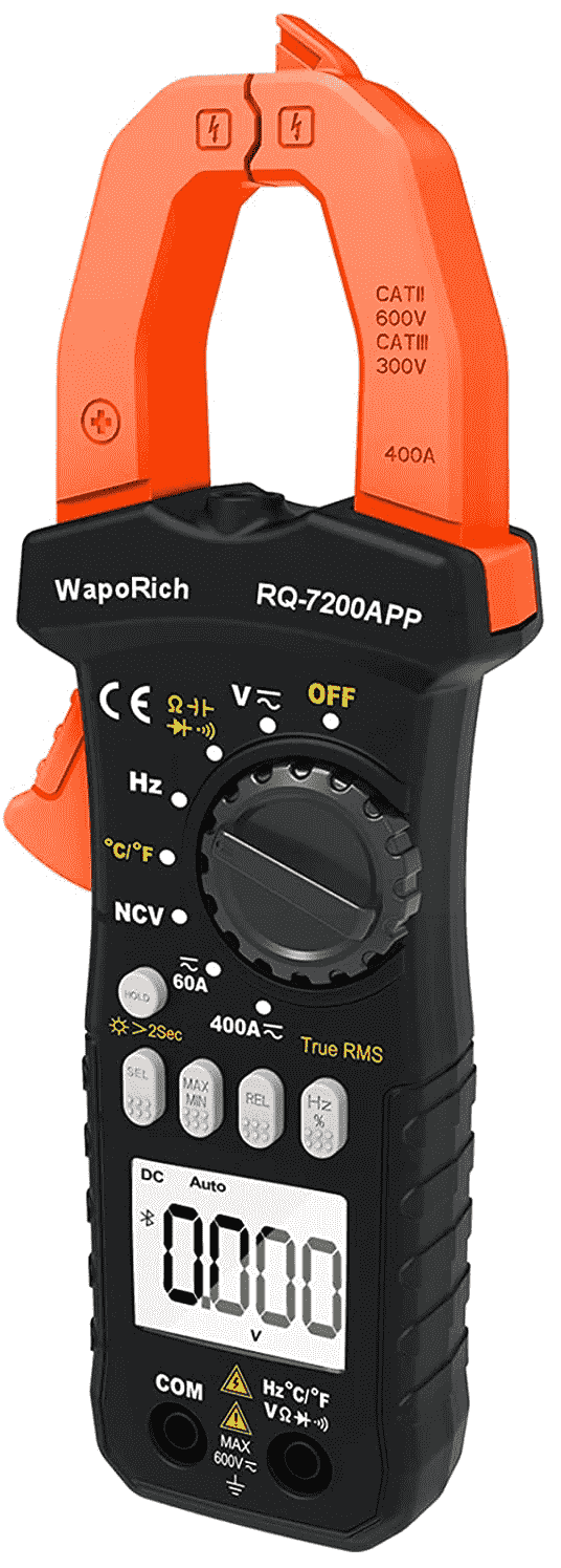
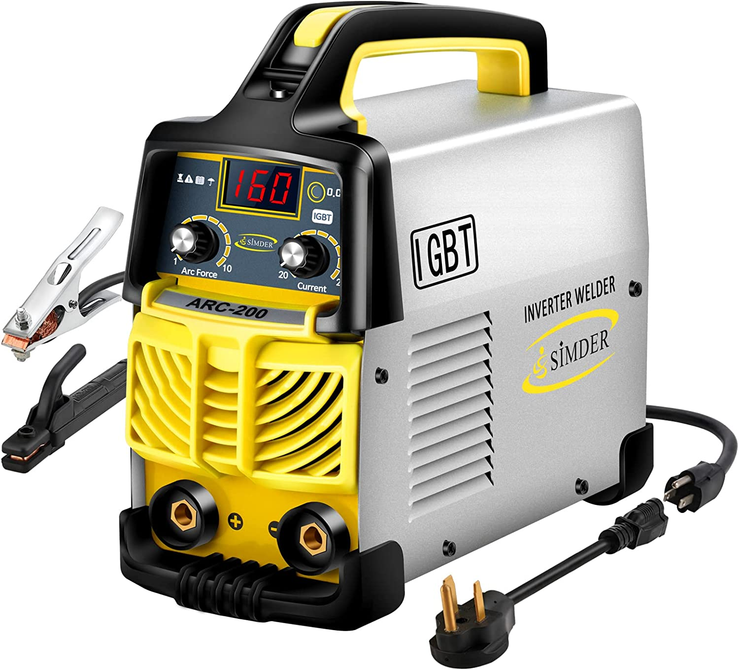
It will be recalled that this is the Simder ARC-200 welding machine, costing $70. It is 9.3 x 3.9 x 7.5 inches in size and weighs 11 pounds. It will be recalled that I measured the DC welding currents using a WapoRich RQ-7200APP clamp-on ammeter, costing $43. It transmits its readings via Bluetooth to a smart phone where the readings got logged.
Skipping ahead to the answer, here are the results:

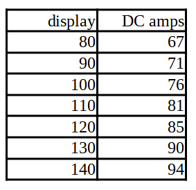
With “80” appearing on the display, the welding current was 69 amps. With “140” appearing on the display, the welding current was 96 amps. For values between these two end points, as you can see on the graph, the response was very close to linear. I did a linear regression on these seven data points, and the function turned out to be:
current = (display * 0.457) + 30.3
In other words, had we extended the line toward the Y axis, the Y-intercept would have been about 30.3 amps. A practical consequence is that the current/display line absolutely does not pass through the origin.
It will be recalled that this welder is made so that it can run on any supply voltage in the range of 90 VAC to 260 VAC, and the frequency can be your choice of 50 Hz or 60 Hz. (The welder automatically adjusts to whatever supply voltage is provided.) The measurements just described were obtained with the welder running on 240 VAC.
The natural next question is what happens if we power the welder with, say, 120 VAC instead of 240 VAC? I carried out these measurements and it was an exact match. Another way to say this is that the number on the display can be mapped to a value of DC welding current and the mapping will be the same regardless of which of the two supply voltages is provided.
The welding voltage, according to the documentation, is in the range of about 21 to 26 volts. (In a future measurement project I will measure some welding voltages to see if this is accurate.) This is consistent with what web sites say about typical stick welding voltages. The middle of the range measured above was around 82 amps, so if we assume (say) 24 volts, this amounts to around 2 kW of power being delivered to the arc. This machine claims to have a conversion efficiency of 85%, which suggests that the welder might have been drawing around 2.4 kW from the receptacle. At 240 VAC, this would mean a draw of perhaps 10 amps. At 120 VAC, the currents would be double this, perhaps around 20 amps. (The 120-volt receptacle that I was using had a 20-amp circuit breaker, and it did not trip for any of the settings shown in the graph above.)
Which brings us around to a practical result. I printed out this table on paper, and I taped it to the side of the welder:
One Reply to “Welding current redux”